As part of the Audio Augmented Reality project, we did a pair of workshops as a way of discovering avenues for technologies that people might be interested in. After reviewing the transcripts and having some general discussions with the other team members, I decided to start making a gestural system for placing sounds in 3d space.
Implementation
The system is to difficult to explain, so I made a quick video.
Future Work
I'm going to do some of the things I said in the video. And I am going to work on some other prototypes of different systems.
It's the future. The Exciting Future Of Technology. Tomorrow. Innovation. Science. As long as I have this thing on my face I can't even see the past. I want to have my natural senses revoked. And replaced by car adverts if possible. This is definitely going to make everybody's life better. EverybodysLife™ Here, put this big pacifier in your mouth and stop asking questions. My vision of the future is probably universal, so maybe I should keep trying to make it everybody's future.
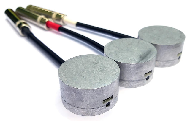
Introduction I used the Hsu-Nielson method to find the frequency response of my contact microphones. This method involves cracking a mechanical pencil graphite on the microphone transducer. The microphone in question is the one shown above, and described in detail here: http://michaelkrzyzaniak.com/marshmallow.php I specifically used the white, low-gain variant. Experimental Setup and Results Figure 1: The mechanical pencil used in this experiment, with 0.5mm number-2 graphite Figure 2: Three millimeters of graphite were extended from the pencil Figure 3: Audio interface used for experiment (Scarlett 2i4), showing the settings used. Figure 4: Video showing the graphite being cracked. A small amount of putty was used to prevent the tip of the pencil tapping the transducer after the graphite breaks. The graphite is placed on the transducer and constant pressure is applied. When the graphite breaks, the pressure is released in a very short ti...
Figure 1: Sound Sphere in the Center for Vision, Speech and Signal Processing (CVSSP) at the University of Surrey. The person is shown standing in the intended orientation, facing the front of the sphere. Introduction I recently needed some audio content that I could quickly render for playback in the sound sphere shewn in Figure 1. There are a reasonable amount of free ambisonic recordings available online, e.g. Angelo Farina Youtube So I spent some time putting together tools to render ambisonics in the sphere, and here I wanted to share what I learned in case anybody else at CVSSP wants to try this out in the future. Speaker Arrangement The sphere has 24 speakers (plus a subwoofer which I will henceforth ignore), which at the time of writing are arranged as shown in Figure 2 and Figure 3. Figure 2: Speaker layout. The center of the diagram represents the top of the sphere. The top of the diagram represents the front of the sphere. Th...


Comments
Post a Comment